This post will contain simplified examples and explanations at the cost of absolute technical accuracy.
Preface
In today’s world the amount people getting connected to the internet is a number which is rapidly increasing. At the same time application requirements on the network are reaching new highs. The underlying networks must be able to facilitate this large amount of data that is required to be transmitted and received by many users simultaneously.
There are many aspects to network capacity and how fast data can be moved through the network and fibre optics are a key component in this. Optical communication allows for very low latency and higher throughput communications at longer distances as opposed to the mediums is supersedes, such as twisted pair cabling.
Thanks to technology like Coherent Optics we are able to reach higher peaks in speeds deployable in the network. Speeds like (at the time of writing) 1.6Tb/s.
The motivation for this post is driven by an interest in fibre optics and what I observe as a general lack of discussion about fibre Optics in Network Engineering communities online.
Pluggable optics
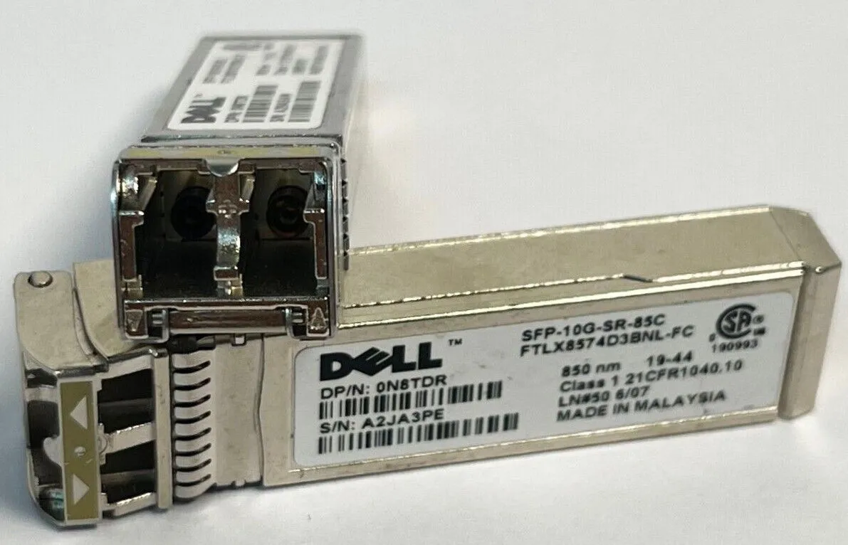
Many who deal with fibre optics in one way or another are likely to have encountered an SFP (or some variant of it), SFP stands for Small Formfactor Pluggable. These fall under what’s known as pluggable optics.
Pluggable optics, as the name suggests are optics which are designed to be plugged & unplugged. The important part is the optical component of this is that the pluggable optic will perform the electrical conversion of (the 1’s and 0’s) into the optial signal to be transmitted across the fibre.
There are also embedded and co-packaged optics, which are out of scope of this post. They retain the similar components and principals.
The key components inside the pluggable optics are:
- The light source, this is generally some type of laser.
- Something to read the light, called a photodetector. Converts the light into an electric signal.
- Processing equipment, usually a DSP (Digital Signal Processor). The signal processor handles conversion of the analog signal into a digital signal and vice versa. It performs additional functions for features like error correction.
Optics are where the ‘magic’ happens, where the light gets manipulated to generate the signal which represents all those ones and zeroes. Different optics will perform this manipulation of light in different ways, which have their own advantages and disadvantages.
SFP superseded what was known as a GBIC. There also exist less well-known formfactors such as OSFP and CFP.
Encoding methods
Data in computer networks are represented in binary bits. Transmission of this data is creates a digital signal. From an optical perspective light is an analog signal. This means sending data across fibre optics requires that the light is manipulated in some way so that it represents a digital signal.
A common analogy is to think of the laser in the optics as a flashlight. Switching the flashlight on and off in a certain pattern, such as morse code; could be used to communicate some information to somebody who can see and understand what the flashes of light translate into.
In this analogy what we modulate is the light (whether it is on or off), and morse code is used as our encoding method. Encoding method meaning what sequence of light modulation translates into what information.
The encoding method is important as each different method have their own different limitations to factors such as speed and signal quality.
NRZ coding and symbols
The first method of encoding discussed is called NRZ. NRZ is quite similar to the flashlight analogy.
NRZ is also known as PAM2.
- NRZ stands for Non Return [to] Zero
- PAM2 stands for Pulse Amplitude Modulation 2-levels.
With a digital signal only two states can be represented by the wave, either on or off. This translates into binary with the two bits being 1 and 0.
Using NRZ encoding there are two states the wave can be in to represent data. These states are a high and a low amplitude of the wave. This is why PAM2 is a much more apt name, there are two levels of amplitude that the wave can be modulated between.
Each possible state the signals waveform that represents some data is referred to as a symbol. Using NRZ this would mean we have 2 symbols.
Symbols tie into a value known as the baud rate. The baud rate is the number of symbols able to be transmitted per unit of time. This is not to be confused with the bit rate, which is how many bits you can transfer per unit of time.
For both baud and bit rates the common unit of time is 1 second, or per second.
The baud rate can be calculated as:
You can calculate the bit rate from the baud rate as:
In the case of NRZ two symbols, representing a single bit each means that the baud rate is equal to the bit rate (or 1:1). For example if the baud rate of a system using NRZ encoding is 10GBaud, the bit rate will be 10Gbps.
NRZ has no neutral state, this means the wave will always be representing either a 1 or 0. The receive side decodes the signal by sampling the light at a pre-set time interval, or at each clock cycle. Every clock cycle the received light’s amplitude will be measured to determine whether a 1 or 0 was transmitted.
Below is a diagram of a digital NRZ waveform.
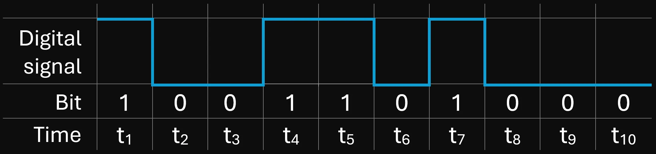
The diagram shows a digital signal, however the light wave is analog in nature. Light is unable to instantaneously or perfectly change states between high and low amplitudes, or on and off. In the analog waveform there will always be some gradual transition between the states.
NRZ style encoding practically maxes out to 28GBaud, meaning 28Gbps maximum bitrate.
PAM4
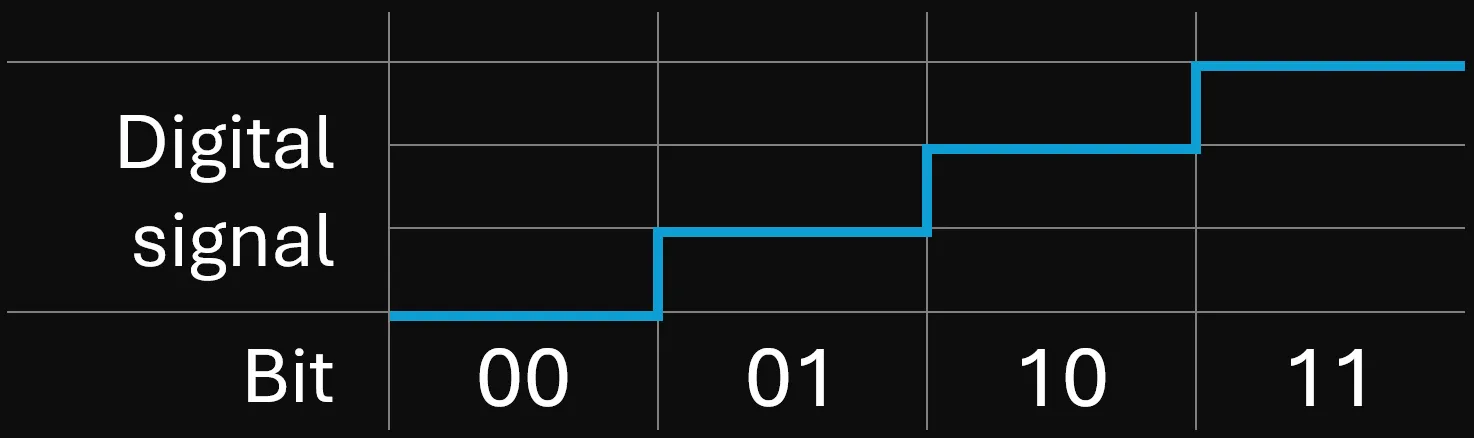
A more advanced type of encoding using amplitude modulation is PAM4. Pulse Amplitude Modulation 4-levels. PAM4 uses 4 levels of amplitude to represent data, meaning 4 symbols.
Having 4 symbols means that two bits per symbol can be represented. This instantly doubles the bit rate from NRZ (assuming the same baud rate).
Below is a diagram which represents the 4 symbols and shows an example of what values the two bits per each symbol may represent.
Below is another diagram which shows how data may be transmitting using PAM4 encoding. Notice that the same 10 bits used in the NRZ diagram are transmitted however 5 less clock cycles are used. The result is the same data is transmitted in half the time, or that the bit rate has doubled.
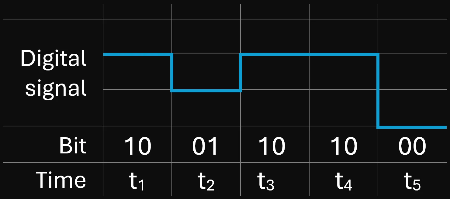
Assuming the maximum 28Gbaud that is common with NRZ, using PAM4 encoding would result in an effective bit rate of 56Gbps.
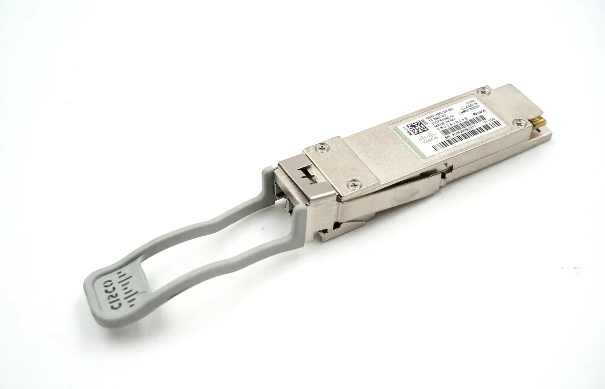
With optics such as QSFP-DD providing an 8 lane interface, this means 8 lanes at 56Gbps (assuming 28Gbaud), means speeds of 800Gbps can be reached.
Drawbacks
With both PAM4 and NRZ there exist drawbacks, largely due to the nature of data being encoded purely by modulation of amplitude.
- Speed is limited by how fast you can modulate the amplitude (or intensity) of the light.
- Both methods are susceptible to issues from different types of loss and dispersion in the fibre. Each pulse of light will lower in amplitude and get closer to each other across increasing distances and eventually overlap rendering the signal useless. PAM4 is more sensitive to this compared to NRZ.
- Using these style of encoding methods on optics with increased lane counts (QSFP or QSFP-DD) results in the optics performing WDM. WDM optics are much more costly, and this is poor usage of the light spectrum.
- For PAM4, more advanced optics are required to generate and process the signal. Higher requirements in optical capability means higher cost.
- For PAM4 a higher transmit power is required for the signal to propagate across longer distances, higher power optics means more heat generated and higher cost. Practically speaking this places a limit the maximum distance of fibre that can be used versus NRZ.
Coherent optics
High bit rates can be achieved using PAM4 encoding but the implications relating to speed and signal degradation are problematic for carrier grade networks.
Light has many physical properties and PAM4 and NRZ only use one property of this, being the amplitude (or intensity). Using other properties of the light can effectively remedy the major issues that existed with PAM4 & NRZ.
Previously with PAM and NRZ, modulating only the amplitude (or light intensity) is known as direct detect. The newest style of detection is called Coherent detection, where properties of the light such as the phase and polarisations of the light wave are taken advantage of.
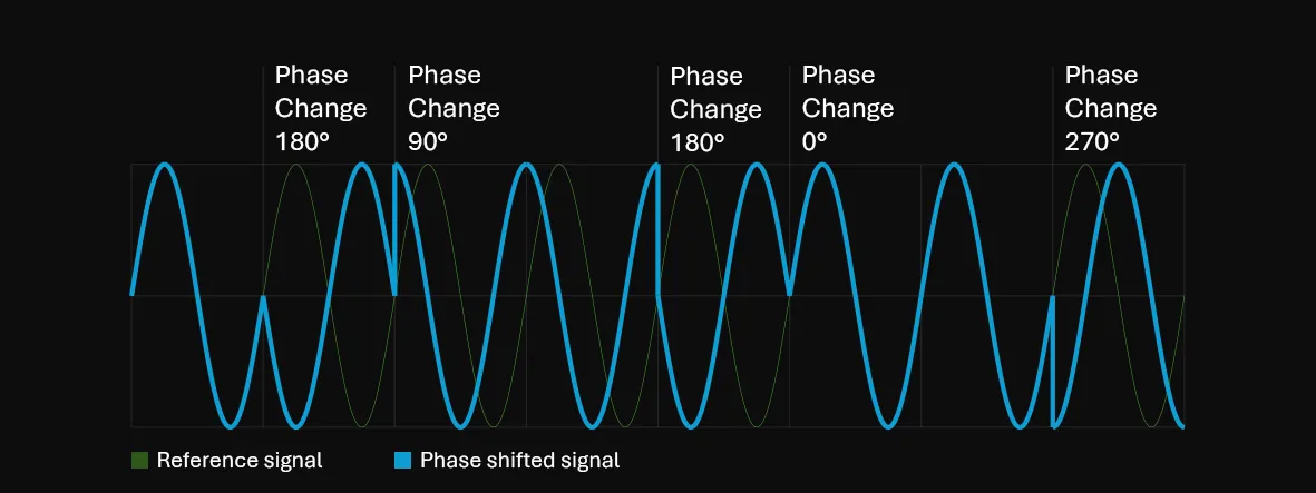
Changing the phase of the analog light wave is referred to as phase-shift keying. Modulating or shifting the phase of the light wave by degrees can represent a symbol. If you assume a phase shift, that means 4 symbols can be represented.
The optics will generate an internal reference signal to compare against the received signal and deduce whether a phase shift has occurred. The diagram below illustrates this.
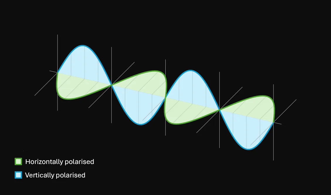
Wave polarisation is the direction the wave faces on the horizontal/vertical axis. The polarisation is not modulated to encode symbols but rather in a manner of multiplexing. Using polarisation multiplexing is conceptually similar to WDM, where you can transmit using multiple wavelengths over a single fibre. Multiplexing with polarisation means we can multiple different signals onto a single wavelength of light.
There exist two polarisations that are used, the horizontal (x) and the vertical (y) polarisation. Using two polarisations means the data rate is doubled across a single wavelength.
The diagram below illustrates the same wave being sent across a horizontal and vertical polarisation.
QAM
QAM, or Quadrature Amplitude Modulation; Is the type of encoding used in Coherent optical transmission. QAM combines modulation of both the amplitude and phase, which allows us to push more data across a single wavelength of light.
An example of QAM usage is in applications such as RF (like WiFi) and DOCSIS (Cable TV/Internet).
With QAM two waves are used:
- An In-phase wave called the I wave.
- A wave out of phase by , called the Quadrature-phase wave or Q wave.
The I and Q waves modulate both their phases and amplitude to transmit information.
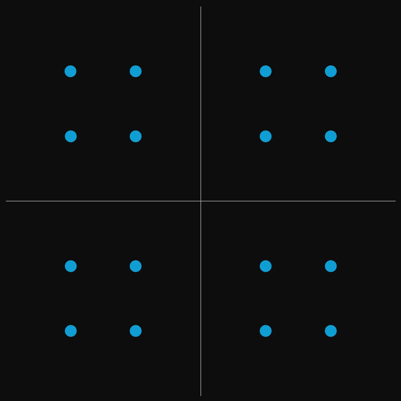
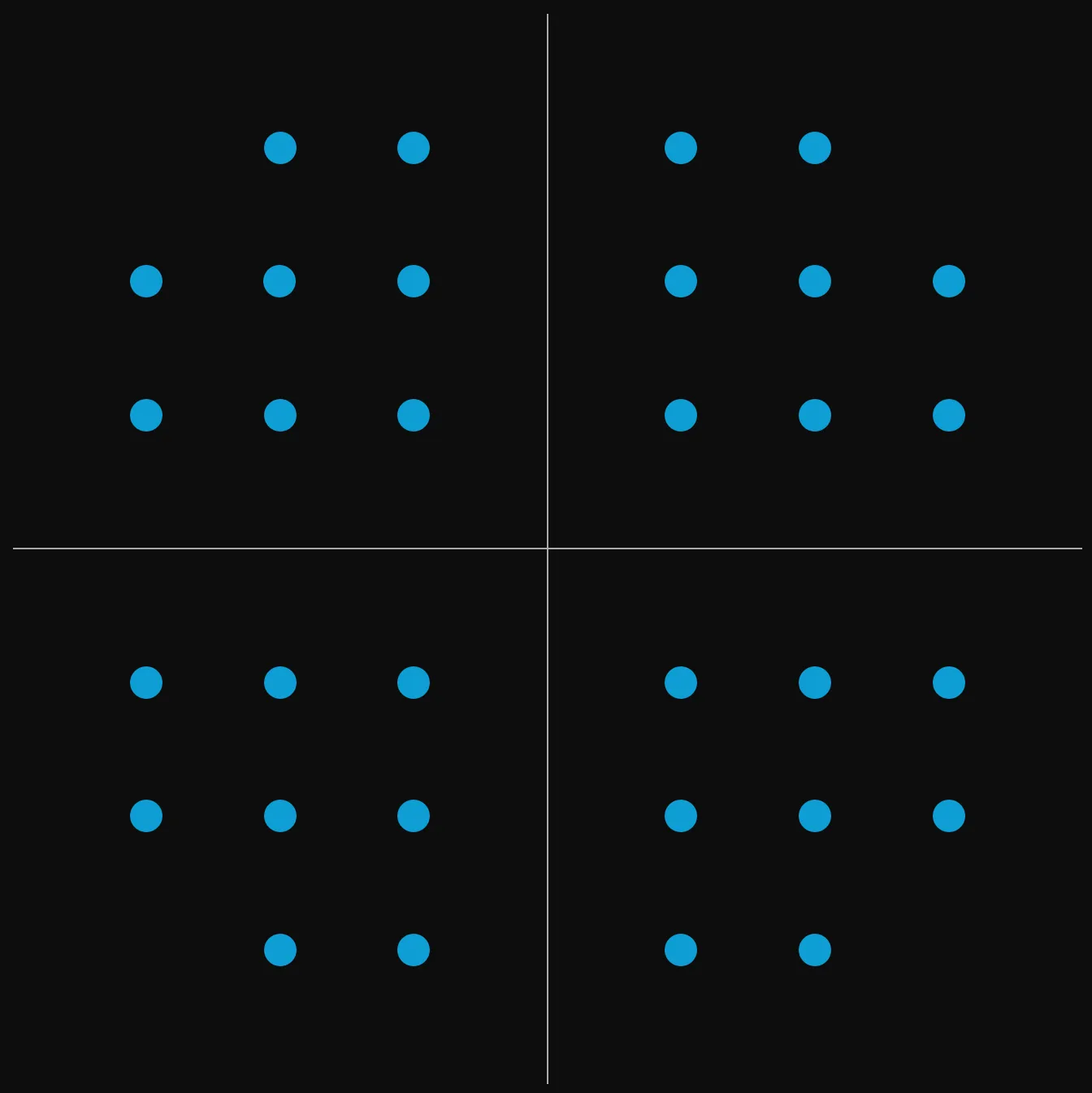
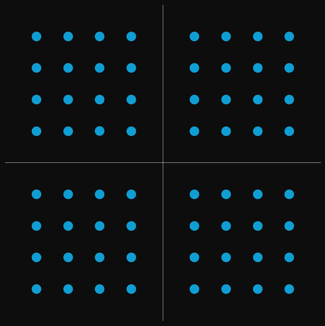
To represent QAM encoding, a constellation diagram is used. The constellation diagram plots the I and Q waves in a way that you can measure the amplitude and wave phase. Each plot on the diagram is referred to as a constellation.
QAM comes in flavours which increase by the power of 2. For example in Coherent optics today, 32-QAM in used. This means there are 32 possible combinations of amplitude and phase which represent some data, or 32 possible symbols.
Below are illustrations of a 16-QAM, 32-QAM and 64-QAM constellation diagrams:
The number of binary bits per symbol/constellation is calculated as . Where is the number of constellations or symbols.
In 16-QAM, there are 4 bits per symbol. This means the bit rate will be doubled compared to PAM4. Using 32-QAM which has 5 bits per symbol, we 2.5x the data rate. This is more pronounced with 64-QAM where there are 6 bits per symbol and a tripled bit rate versus PAM4.
Using the 28Gbaud example from earlier, using 64-QAM means a bit rate of:
Adding the secondary polarisation means that number is doubled, our bit rate is 336Gbps on a single wavelength.
The higher the order of QAM you go, the more sensitive the signal is to noise. This means a higher Signal-to-Noise Ratio is required. When plotting a constellation diagram based on real data you will observe slight variation in the x and y position of each constellation point. When the order of QAM increases, the constellation points are much closer. This means variance becomes more of a factor because if a constellation point varies in location too much it may detect as something different from what it was transmitted as.
Baud rates today are much higher than the 28Gbaud example. The article linked in the introductory paragraph mentions a baud rate of 200GBaud. Long haul and high baud rate transmission systems are unlikely to be using high order QAM encoding due to SNR reasons mentioned.
Conclusion
It’s easy to see coherent detection has a large impact on the data transmission speeds, but also improvements on spectral efficiency. More data is able to be transmitted using a single wavelength.
Previously it was few and far between to find Coherent technology inside pluggable optics. This meant vendor lock-in and requirements for large, complicated and expensive chassis style systems as line cards were (and to some extent still are) the only format you’d find high end coherent optics capable of 800G+ speeds.
Today pluggables with coherent technology are rising in prevalence. Standardisation initiatives like OpenZR+ facilitate vendor interoperability for high performance and long-haul distances of 400+ kilometres.
The major implication of coherent pluggables being available for long distance circuits is that in greenfield networks a large CapEx sum for OTN networks isn’t necessarily required. Plugging directly into an L2/L3 device means reduced maintenance and footprint. L2/L3 hardware is also starting to push the limits of speed causing optical speed to bottleneck. Aligned with the boom in silicon globally (as a result of A.I processing needs) there is now 1RU hardware which can route at many Tb/s.
From an OTN perspective IP/MPLS/SRv6 can provide similar functionality for traffic multiplexing and private-line services and we can see that vendors are pushing for tighter integrations between the optical transport layer and Layer 3. That’s not to suggest that this is a be all and end all replacement for traditional OTN chassis systems which very much still have a place in networks of today and the future.
In terms of the future, time and time again the bit & baud rates have increased despite what we think is possible. One way or another the technology will have to facilitate higher demand on the network and only time will tell when the limits are truly reached.